
So over the course of yesterday and today I laid out and cut the front panel for the cabin on the Lady Jane. This was a tricky bit of work, as it was set at an angle, intersecting a curve on the top and bottom of the piece and the two triangles at the side. None of the sides intersected the rest of the boat at right angles or even just simple angles; these were compound angles with curves thrown in for good measure.
While I was talking to some of the people at Fisheries Supply, I described how i was going to do this and realized that this wasn’t your average bit of knowledge; the kind of 2-D to 3-D geometry and layout I had learned in my steel shipfitting apprenticeship seemed to be a mystery to most.
So, I’ve decided to detail exactly how to do this.
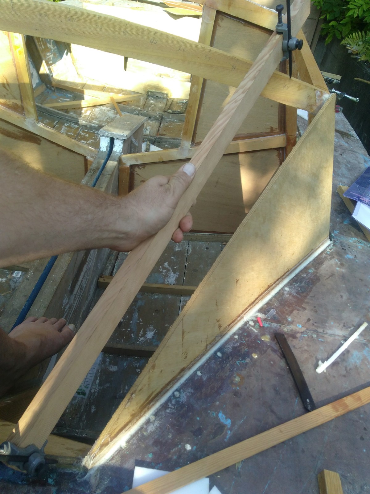
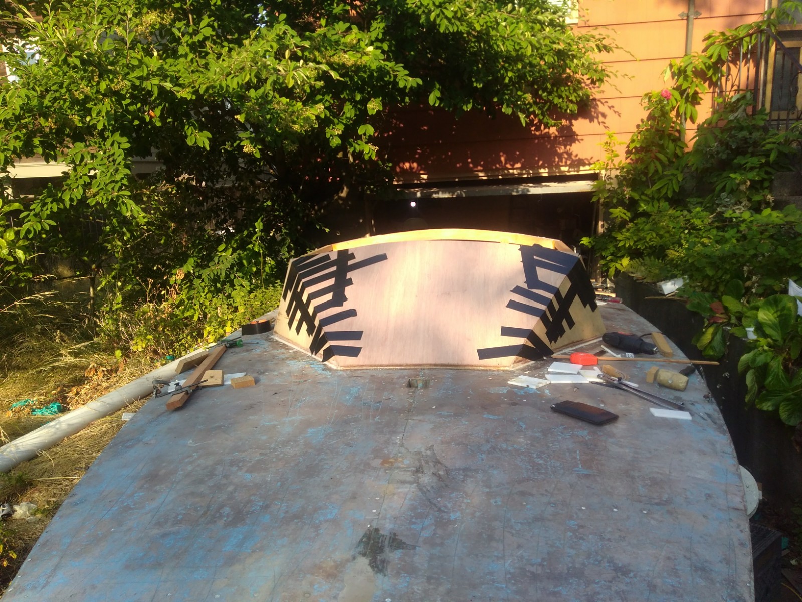
Here’s the hole we need to fit the plywood panel into.
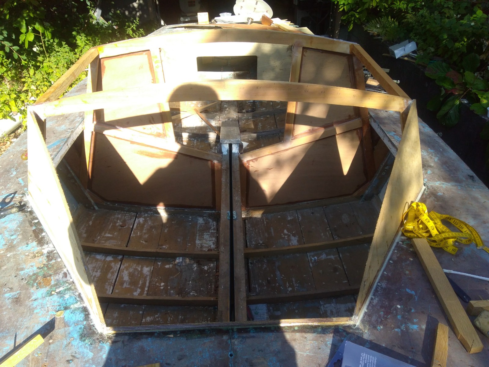
The top and bottom pieces are curved, so the panel will have some shape to it and neither the top or the bottom are straight as a result of this shape and the angles involved. The sides are straight, where they intersect the 3/8 thick triangles on each side.
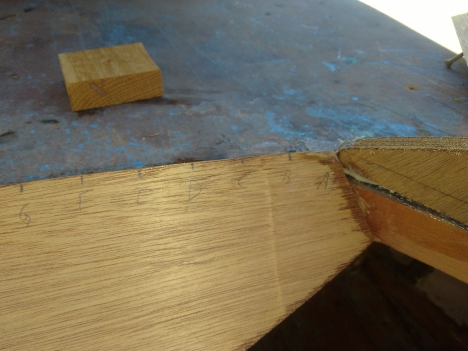
To start off, I swiped my wife’s dressmaking tape measure and measured the arc of the top and bottom pieces. The top piece measured 46 3/4″ and the bottom piece measured 22″. I decided to go with 22 ‘brakes’ in the pieces. So, first i found the centerline of the top and bottom pieces. I then made a mark every one inch on the bottom piece, and every 2 inches on the top piece.
On the bottom, smaller edge these were labeled A, B, C, and so on.
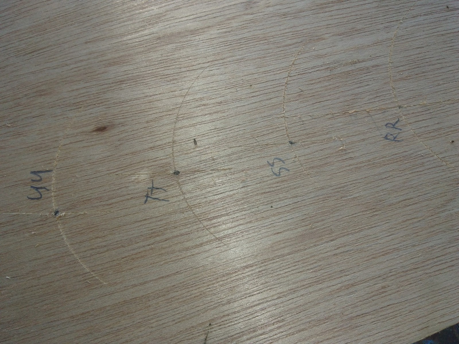
On the top piece, these were labeled AA, BB, CC, DD, and so on.
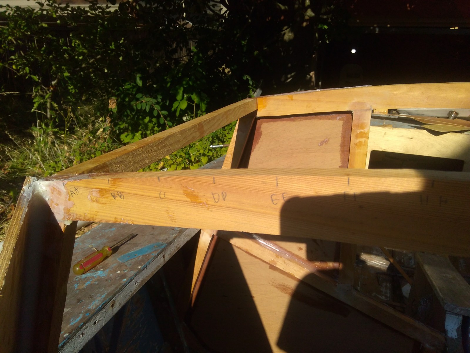
The centerline was Point L on the bottom, and Point LL on the top.
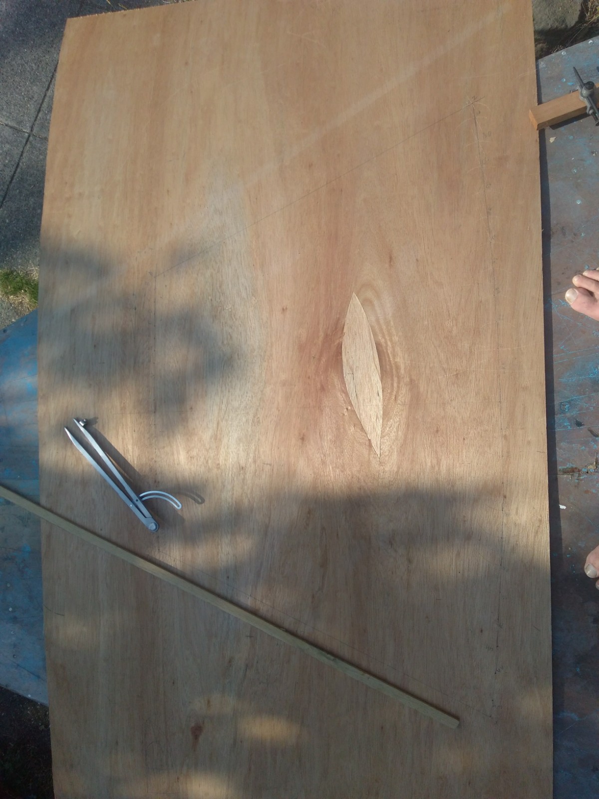
Because marine plywood wasn’t cheap, and this is a tedious bit of layout where one mistake in a hundred step process ruins the piece, I decided to do the layout on a piece of template plywood, then transfer it to the good stuff once I had test fit it.
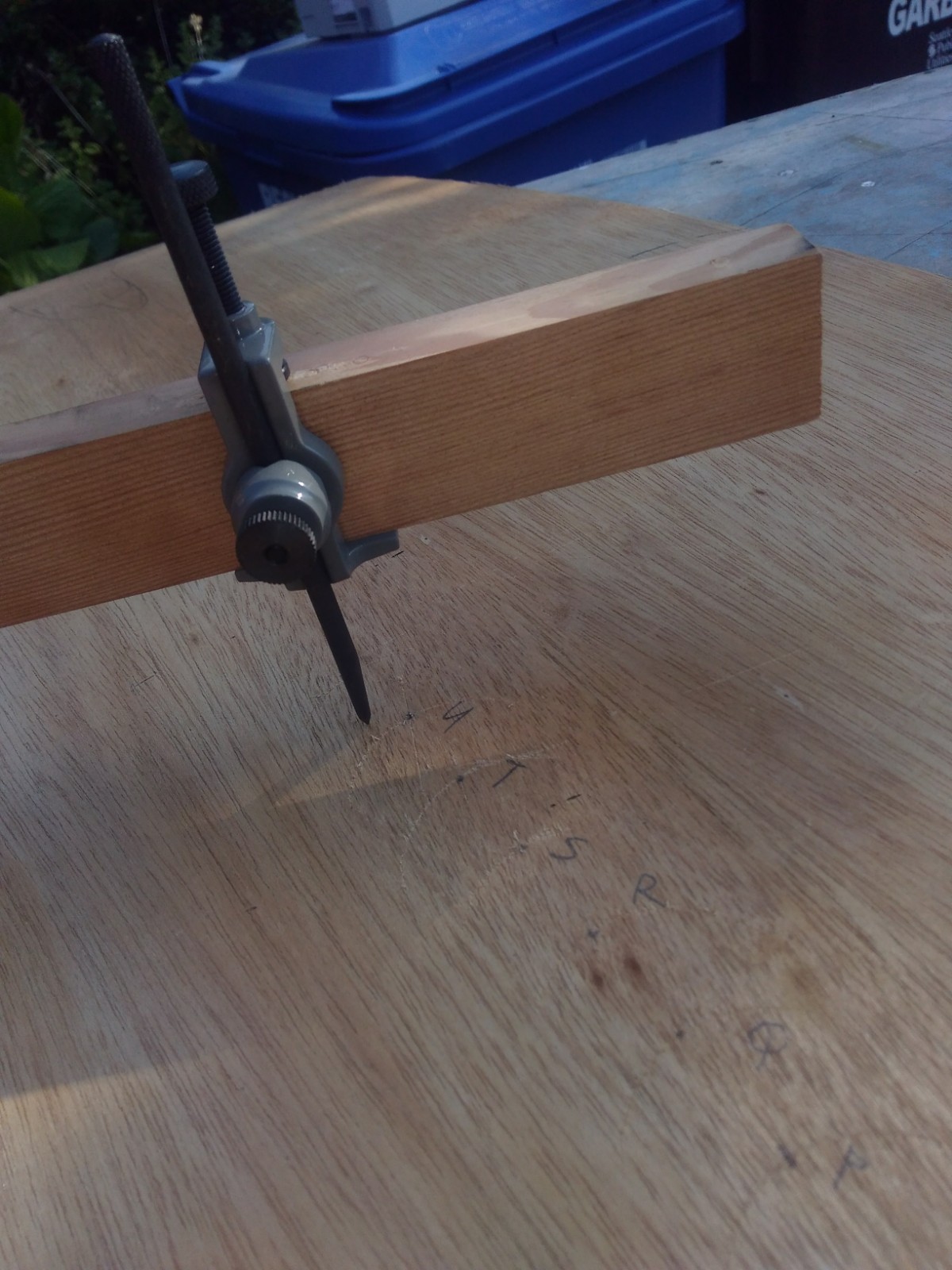
Now, to start. I struck a line perpendicular to the edge. on this line, about an inch from the edge I made a point and labeled it LL. I then set trammel points to the distance from LL to L and transferred this measurement to the line. it is important that the long edge and point LL be on the end closest to the edge, as the edge will curve away from this edge.
From there, I had to take my dividers and strike a 1″ arc on both sides of L, and a 2″ mark on both sides of LL.
I then had to set my trammel to the distance from L to KK, transfer this, then from L to MM, transfer this, then from K to KK, and from M to MM, and so on, and so on. Essentually, we’re converting the curve into a series of triangles; similar to how they render shapes in some video games. once these triangles are all laid out flat, we’ll know what size and shape our piece needs to be to fit the hole once it is wrapped around the curve and in place.
Here’s a few pictures of the process:
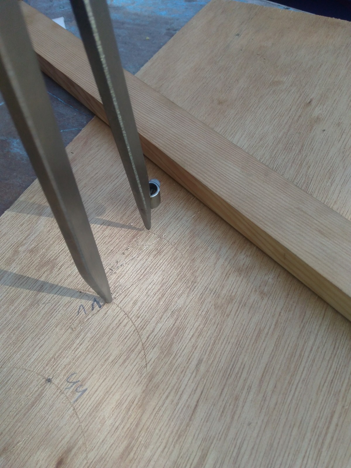
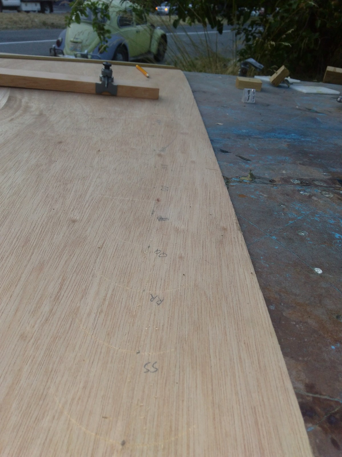
As you can see, a bit tedious, and a ton of steps.
If this were a piece of steel, the lines A to AA thru W to WW would be ‘break lines’ and would be bumped in the press brake to put a slight bend in the plate. these ‘breaks’ would then approximate the curve.
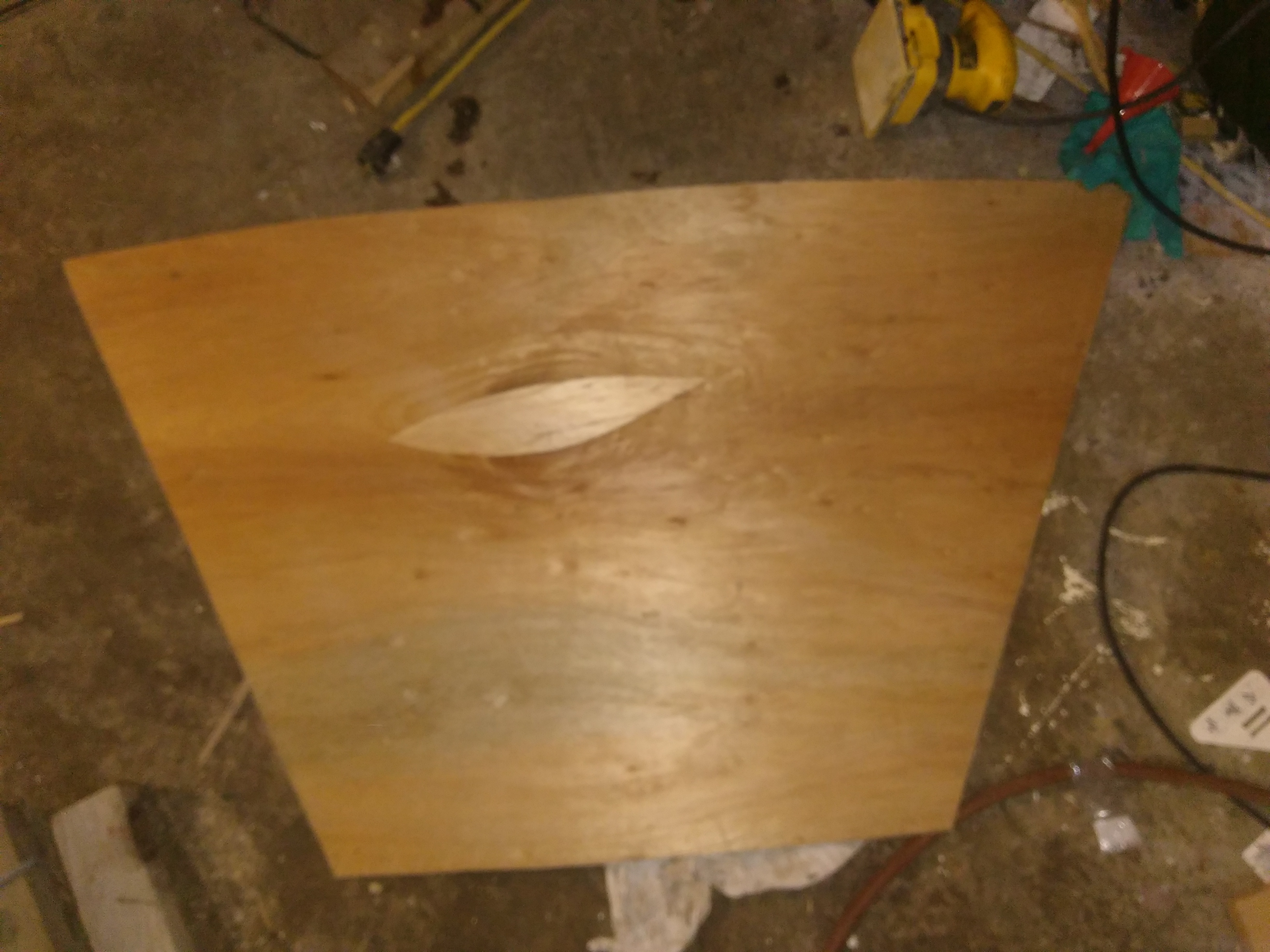
It all came out in the end. here’s the template:
And here it is, piece cut and installed in the boat. I’m using a trick I learned from Michael Storer’s Oz racer plans, and using duck tape to hold the piece in part while the epoxy fillets on the backside cure.
I hope I made this clear. Feel free to ask any questions in the comments and I’ll elaborate if i have to.